Printed enclosure for the modular carrier
This prototype case fits the 160 × 70 mm pill carrier with the eight-pin HOTHMI display and socket-mounted Luckfox Mini. The outside is 176 × 82 mm, with a removable rear service cover. Digital fit and slicing checks cover the current CAD assembly; verify the purchased camera and a first print before assembling the full device.
Load the 3D model to inspect the case and PCB together.
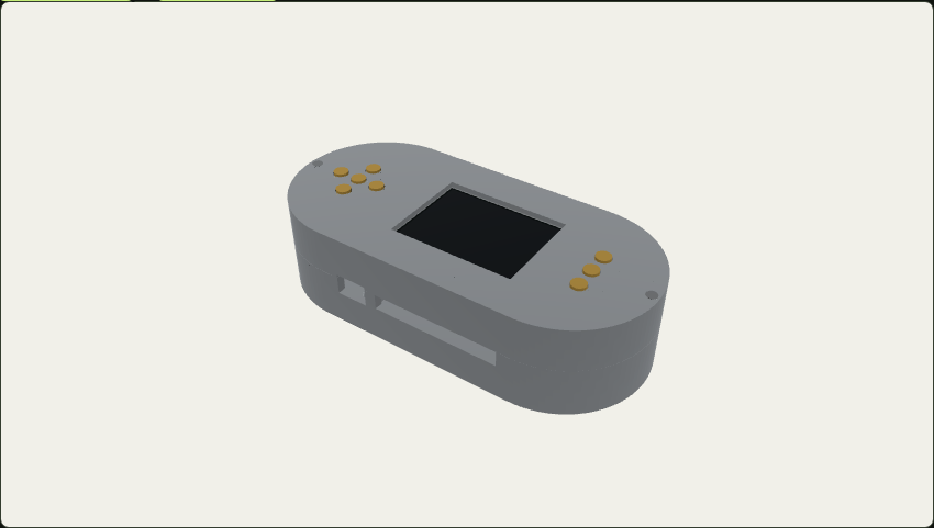
Download either GLB below to inspect it in a 3D viewer.
Camera and ribbon are adjustable envelopes. Screw threads are omitted. Digital clearances do not replace a first fit with the purchased parts. Static exploded view ↗

Parts and printing
The design follows SeedPills' approach of independent parts with broad, flat print faces and explicit fit clearances. Two shells close with screws. Separate button plungers, retaining plates and camera clamps avoid trapped supports and delicate snap clips.
| Print file | Quantity | Orientation |
|---|---|---|
| base.stl | 1 | Broad rear face on bed |
| bezel.stl | 1 | Broad front face on bed |
| button.stl | 8 | Button face on bed, stem upward |
| retainer-left.stl | 1 | Flat on bed |
| retainer-right.stl | 1 | Flat on bed |
| camera-tray.stl | 1 | Flat support ring on bed |
| camera-clamp.stl | 1 | Flat on bed |
| service-cover.stl | 1 | Outside face on bed |
The portable 3MF contains these 15 independent objects. Start with the P1S, 0.4 mm nozzle, PLA and 0.20 mm layers: four walls, five top/bottom layers and 20% gyroid infill. Supports and prime tower are disabled. The complete plate slices as one plate, approximately 5 hours 30 minutes with the current preset. The saved report records the exact slicer result. Re-slice for your printer and material rather than sending another machine's G-code.
The shells use 2.4 mm faces, vertical walls and a 45° transition into the locating lip. Printed holes may need gentle deburring. Keep the 0.3 mm radial lip clearance and 0.3 mm radial button clearance free of paint or adhesive. Print the small camera pieces first and test the camera fit before committing to the large shells. The optional button-fit coupon has 7.2, 7.4 and 7.6 mm holes from left to right; test a button in the middle hole before printing the bezel.
Fasteners
These quantities replace the standalone LCD screw arrangement when installing this case. Lengths are nominal; check actual head geometry and screw engagement before tightening.
| Hardware | Quantity | Use |
|---|---|---|
| M2.5 female-female spacer, 12 mm long, at most 5 mm outside diameter | 4 | LCD to carrier |
| M2.5 × 30 countersunk machine screw | 5 | Three base mounts and two shell closures |
| M2.5 × 4 pan-head machine screw | 5 | Four LCD top screws and one carrier underside screw |
| M2 × 5 pan-head screw | 5 | Button retaining plates |
| M2 × 10 pan-head screw | 4 | Camera clamp and tray into base posts |
| M2 × 6 countersunk screw | 4 | Rear service cover |
The three long base screws engage the LCD spacers by approximately 6.6 mm. The LCD top screws engage about 2.4 mm, leaving about 3 mm between opposing screw tips in each 12 mm spacer. Do not add thick washers without recalculating engagement. Printed M2 pilots are 1.6 mm; shell closure pilots are 2.1 mm. Form or tap plastic threads slowly, stopping if a post starts to split or the screw bottoms out.
Why one base post is absent
The carrier's upper-left LCD hole lies in the Luckfox USB and microSD insertion path. It retains its LCD spacer, secured to the carrier with the short underside screw, but has no post extending to the case floor. The other three holes form the base mounting triangle. This preserves all four LCD supports while keeping the Luckfox ports clear, without changing the PCB.
The Luckfox connectors are recessed inside the enclosure. The north-edge opening admits the USB plug and microSD insertion path. Remove the rear service cover to reach the card and latch directly; do not force a card into the case opening by feel.
Camera fit
The camera tray reserves a 26 × 26 × 1.2 mm PCB, a centered 14 mm diameter lens with 10 mm front height, and a 16 × 4 × 2 mm rear connector at the ribbon exit. These are adjustable enclosure assumptions, not manufacturer CAD for the purchased low-profile camera. Measure board thickness, lens position and edge components before printing. The 22 mm clear opening captures centered boards with 24–26 mm edges, including a 25 × 24 mm board. Keep the supported 1–2 mm board margin clear of components; the north side is open for the ribbon. Center a smaller board over the aperture and hold it there while tightening the clamp.
The documented low-profile SC3336 listing specifies a 10 mm high camera. The ordinary Luckfox SC3336 camera drawing describes a taller assembly and must not be used as evidence that its lens fits this case. Change camera_board, camera_clear_opening, camera_pcb_thickness and the tray geometry to match the actual module. A board smaller than 24 mm needs a matching tray, rather than tightening the clamp against empty space.
Route the matching Luckfox ribbon with power off, away from screw tips and the card socket. Leave a gentle service loop and verify the connector contact orientation and permitted bend radius for the actual cable. The pink segments in the 3D model reserve a 12 mm wide routing corridor. They indicate free space rather than the manufactured shape or fold pattern of a particular cable. The flexible ribbon's final routing and retention remain a first-article assembly check.
Assembly order
- Deburr the printed parts. Test the locating lip, button sliding fit and camera tray separately. Keep electronics and power disconnected while forming plastic threads; remove all debris afterward.
- Place the camera in its tray with the lens facing the rear opening. Fit the clamp and four M2 × 10 screws. Tighten only enough to retain the board without bending it. Confirm the lens and ribbon exit remain clear.
- Fit all four LCD spacers to the carrier. Secure the upper-left spacer with the short M2.5 × 4 underside screw. Install the carrier on the three base posts and secure it from underneath with three M2.5 × 30 countersunk screws.
- Connect the camera ribbon and install the Luckfox in its sockets. Verify USB plug and microSD access through the service opening. Place the LCD on its four spacers, mate the eight-pin connector and secure it with four M2.5 × 4 screws.
- With the bezel upside down, insert eight buttons from inside. Fit the two retaining plates with five M2 × 5 screws. Each button must slide freely and remain captured when the bezel is turned over.
- Lower the bezel onto the base without trapping the ribbon. Check every button before installing the two M2.5 × 30 closure screws. Fit the rear service cover with four M2 × 6 countersunk screws.
- Confirm card insertion, USB connections, microSD service and a clear camera image. Run the modular bring-up procedure with disposable test data.
The switch drawing specifies 2.5 ± 0.1 mm actuator height and 0.25 mm travel. The nominal button tip has a 0.1 mm rest gap and a 0.35 mm retainer stop, providing 0.25 mm nominal switch movement. Printed tolerances and actual actuator height can change this. Before tightening the shell, verify release and full actuation of all eight switches; adjust plunger length or retainer shims if necessary. Never use a closure screw to force a preloaded button into place.
Rebuild and review
Source geometry is case.scad. Run mise run enclosure:verify for the full ordered build, fit, fastener, button-motion, exploded-model, plate and slicing checks. Run mise run enclosure:build to render the meshes and check manifoldness, bed bounds, print Z, printed-part collisions and reserved access spaces. mise run enclosure:fit checks the native hardware mesh and regenerates assembled/exploded GLBs. The hardware mesh is generated by enclosure/export_hardware.py from the native assembly STEP; its cache must match the current board and models.
For a fresh design checkout, run mise run kicad:setup, mise run variant:lcd:review, mise run enclosure:hardware, then mise run enclosure:verify. KiCad exports require hydrated Git LFS models. The native STEP import can take several minutes; its mesh cache is reused by subsequent enclosure iterations.
enclosure/print_plate.py builds the portable 3MF. enclosure/slice.py resolves the full official Bambu profile inheritance, slices it and rejects a fallback bed size, missing objects or enabled supports. Generated files live in ignored dist/enclosure/; portable source remains in enclosure/.
The hardware collision check retains closed native solids and reserves conservative bounds for open supplier-model surfaces. It does not prove physical print tolerances, thermal behavior, cable durability or switch feel. Confirm those on the first assembly before treating the case as qualified hardware.
Source: docs/ENCLOSURE.md ↗. Documentation describes reviewed evidence; it does not replace physical testing.